Independent reference · No manufacturer affiliation 17 interfaces documented · DC–40 GHz · 50 & 75 Ω Corrections welcome →

Home  /  Articles  /  Page 2

ARTICLES

Explainers, comparisons and info on the parts of this technology that datasheets tend to skip.

Impedance, VSWR and insertion loss

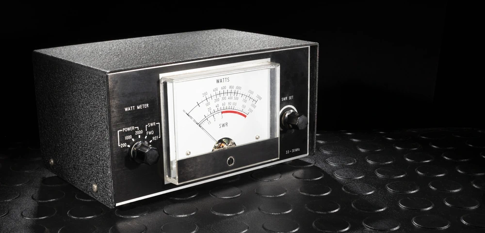
How impedance, VSWR, and insertion loss interact in tiny RF plugs

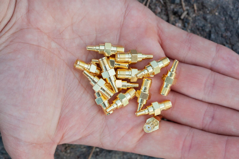
Small connectors get treated like an afterthought half the time. You're routing a board, you get to the RF section, and you slap a U.FL footprint down because that's what fits. Fair enough, space is real and nobody's arguing that. But shrink a connector down to the size of a grain of rice, and the physics doesn't shrink with it. If anything, the margins get tighter.
Common miniature RF connector failures

The little things that break: common failure modes of miniature RF connectors

Anyone who's ever chased a phantom signal dropout at 3 AM knows the particular flavor of misery that miniature RF connectors serve up. You've checked the firmware, reflashed the module, swapped the antenna, and the darn thing still drops packets like it's got a grudge against you. Then, three hours in, you nudge the U.FL cable and the signal snaps back to full strength. There it is. The connector was the problem the whole time.

MMCX and MCX connectors compared

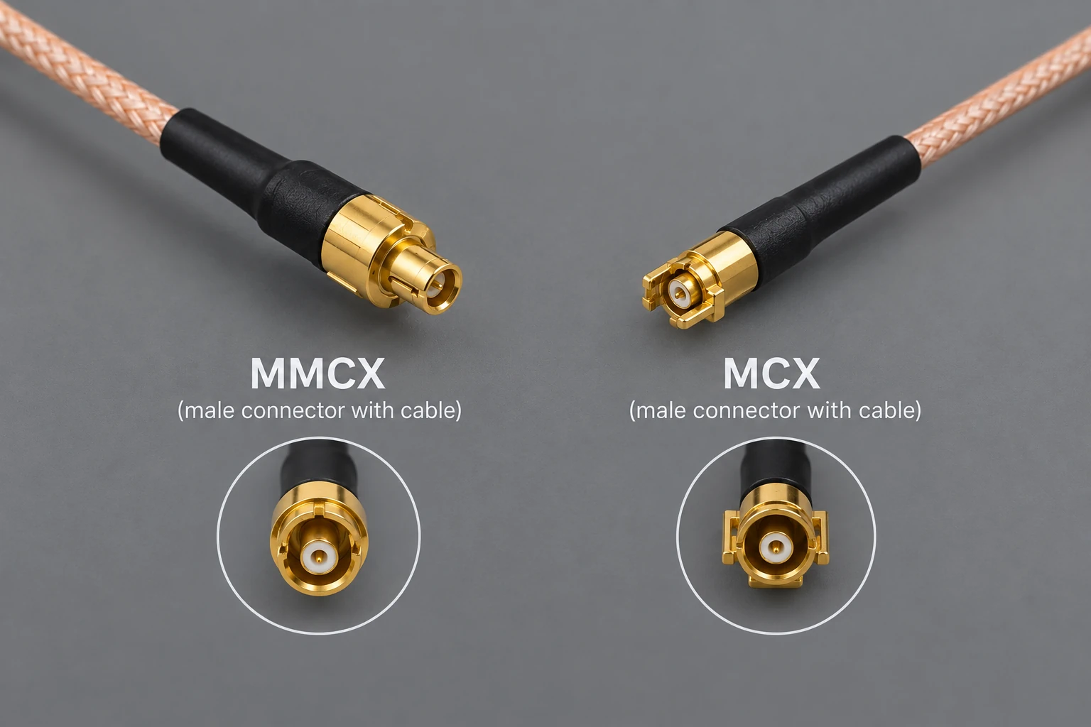
MMCX vs MCX: Real-world differences beyond the datasheet

They look almost identical, both snap into place with that satisfying little click, and yet we've watched technicians grab the wrong one off a bench a dozen times over. Here's the thing nobody tells you until you've stripped a center pin right before a demo: the datasheet is a starting point, not a survival guide. This piece comes from years of us swapping these connectors on prototypes, crying at cross-mate attempts, and occasionally winning. What follows is the version we wish someone had handed us years back, before we learned it the hard way on our own bench.

Identifying unknown RF connectors visually

Reverse engineering unknown RF connectors from close-up photos

Someone drops a photo into your inbox. Zoomed-in, slightly blurry, a metal nub sitting on a green board or dangling off a coax pigtail. "What connector is this?" they ask, and now you're squinting at pixels trying to decide if that's a thread or just a shadow. We've all been there. Maybe you're ordering a replacement pigtail, maybe you're laying out a board and need to match an existing footprint, maybe you're just curious. Either way, there's a repeatable way to work through this puzzle from a single image, and we're going to walk through it. We'll also tell you honestly when a photo simply won't cut it and calipers become mandatory.

SMA and SMP test bench connectors

Why SMA still rules test benches and when to choose SMP instead

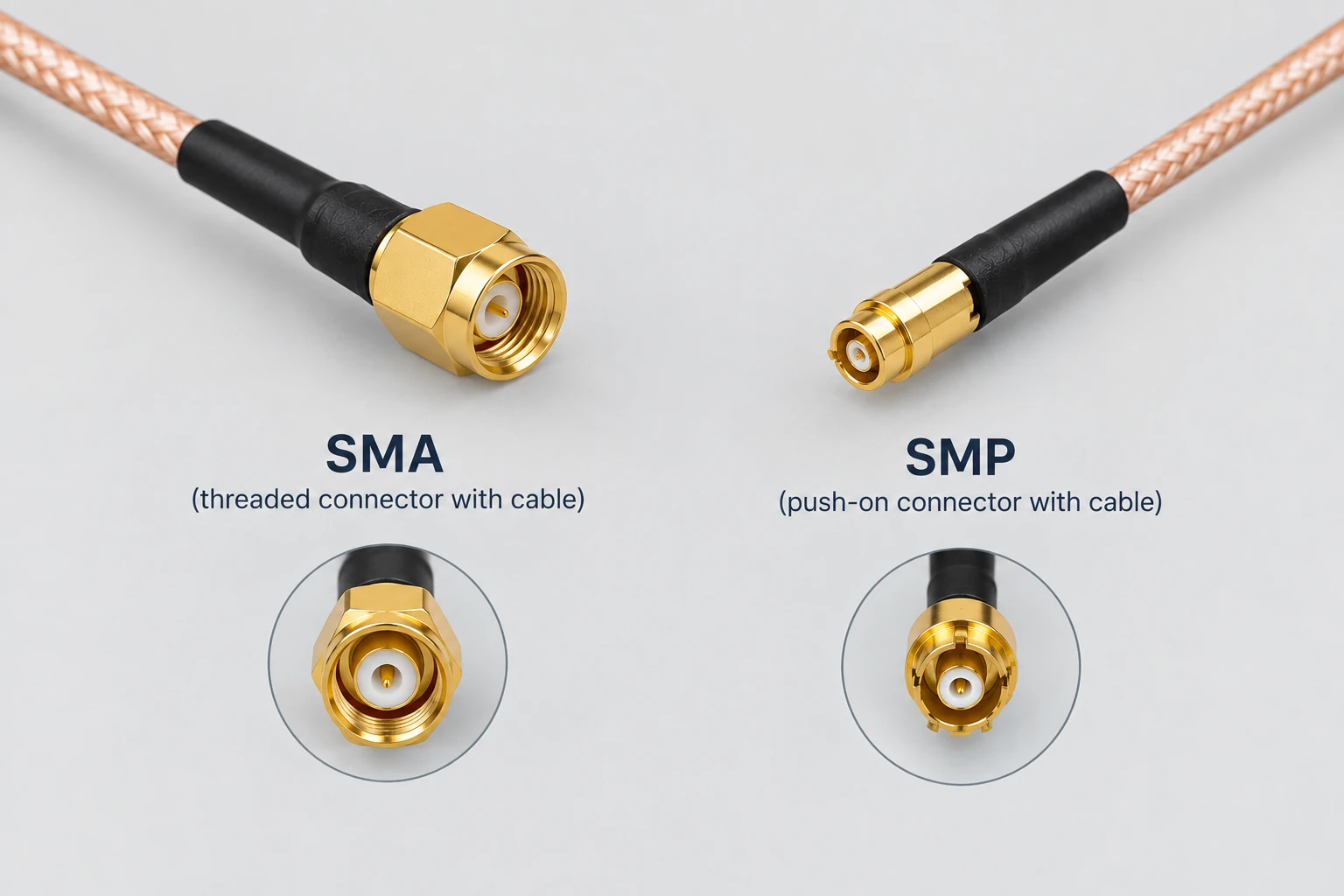
Walk into pretty much any RF lab in the country and you'll trip over the same thing: a drawer stuffed with SMA patch cables, half of them coiled wrong, all of them still somehow working after a decade of abuse. Meanwhile, over in the automated test cell down the hall, something quieter is happening. SMP connectors are sliding into place, no wrench required, no fuss, no drama.

U.FL PCB layout and footprint

U.FL (IPEX/MHF) on your PCB: layout tips and gotchas for reliable RF performance

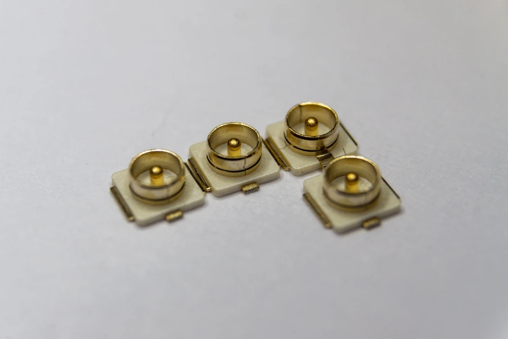
Here's a scenario that plays out weekly in some lab somewhere: a board comes back from fab, populated, powered up, and the RF link is garbage. Range is half what it should be. Someone spends three days chasing firmware bugs before anyone even looks at the connector footprint. Turns out the ground stitching was an afterthought. That tiny U.FL jack, barely bigger than a grain of rice, had been treated like any other component drop instead of the RF-critical part it actually is. This piece is our attempt to save you those three days.

Page 2 of 2

Stay current

We tell you when the reference changes.

Fresh comparison data, cross-reference revisions, corrections. Once a month, give or take. Nothing is sold here, so you are not sold either.