The little things that break: common failure modes of miniature RF connectors
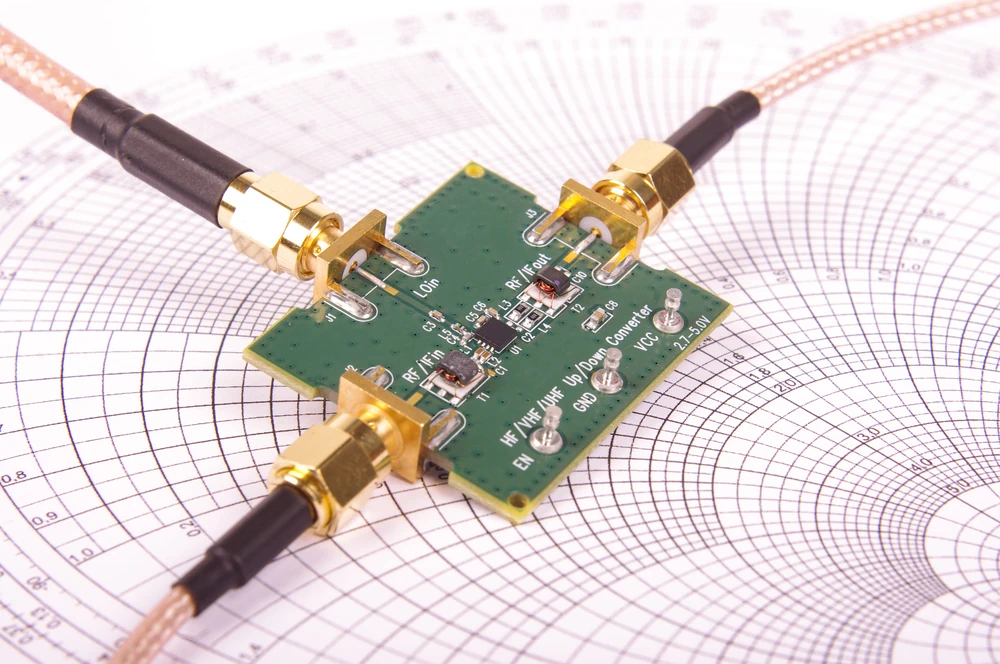
Anyone who's ever chased a phantom signal dropout at 3 AM knows the particular flavor of misery that miniature RF connectors serve up. You've checked the firmware, reflashed the module, swapped the antenna, and the darn thing still drops packets like it's got a grudge against you. Then, three hours in, you nudge the U.FL cable and the signal snaps back to full strength. There it is. The connector was the problem the whole time.
We've seen this scene play out more times than we care to admit. Miniature RF interconnect, the MMCX, MCX, U.FL, MHF, SMA, SMB and SMP families that live inside everything from IoT gadgets to test benches, looks unassuming. Small, cheap, easy to overlook. But these little parts carry precision-tuned impedance across a mechanical interface the size of a grain of rice in some cases, and that combination of tiny scale and electrical demand makes them surprisingly prone to trouble. Weird VSWR readings, mangled center pins, connectors that look mated but aren't really doing their job. This piece walks through the failure modes we run into constantly, how to spot them before they cost you a debugging weekend, and what actually helps.
What we're talking about when we say "miniature"
Scope-wise, we mean U.FL / IPEX / MHF, MMCX, MCX, SMA, SMB, SMP, and their various offshoots and knockoffs. These show up on board-mounted RF modules, pigtail cables, small antennas, and test jigs where space is at a premium. SMA sits at the larger end of this group and still gets lumped in because it mates so often with the smaller stuff through adapters.
Here's the thing worth remembering before we go further: scale changes behavior. A connector rated for 500 mating cycles behaves nothing like one rated for 5000. The physics of contact wear doesn't care that your PCB space budget forced you into a U.FL footprint.
Why these things fail in the first place
Mechanical wear is the obvious culprit. Every mate and unmate cycle grinds down plating, fatigues springs, and shifts tolerances a hair further from spec. Off-axis loads, someone yanking a cable sideways instead of straight out, accelerate this dramatically.
Electrical degradation follows right behind. As contact surfaces wear, resistance creeps up, insertion loss rises, and VSWR starts wandering somewhere it shouldn't be.
Then there's the environmental side: corrosion from humidity or salt air, flux residue nobody cleaned off, dielectric breaking down under thermal cycling. Add to that a healthy dose of human and design error, wrong PCB footprint, missing strain relief, someone torquing an SMA like it's a garden hose fitting, and you've got a full roster of ways these connectors go sideways.
Common failure modes, sorted by what you'll actually notice
Intermittent connectivity is the classic headache. A partial mate, a bent center pin, a spring contact that's lost its spring, some grime sitting where metal should touch metal. You'll see it as fluctuating RSSI, odd noise bursts, reflection spikes that come and go depending on temperature or vibration.
Permanently elevated insertion loss or VSWR tells a different story. This usually points to physical damage: a crushed mating face, a displaced center conductor, cracked dielectric. Pull up a return-loss plot and you'll often see narrowband degradation that's consistent and repeatable rather than flickering.
Mechanical retention loss shows up as connectors that rotate freely or just fall out. Snap-on types like MMCX and MCX are especially vulnerable here since their retention depends entirely on a spring latch that wears with each cycle. Threaded SMA connectors resist this better, though cross-threading creates its own special misery.
Physical damage to mating faces happens constantly in the field. Someone mates a connector off-axis, forces it, uses a tool that wasn't meant for the job, or tries to pry loose a stuck cable with a screwdriver. Bent pins, gouged outer conductors, cracked dielectric follow.
Cable-side failures deserve their own mention. Strain relief that's inadequate lets flexing concentrate right at the cable exit, and that's exactly where cold solder joints and marginal crimps like to crack. These micro-fractures don't announce themselves immediately; they worsen gradually under vibration until one day the connection just opens.
Corrosion and contamination sneak in through flux residue, ambient humidity, or conformal coating that accidentally creeps onto mating surfaces during assembly. The result is a slow rise in contact resistance punctuated by weird intermittent opens that seem to correlate with temperature or humidity swings.
Then there's the sneaky one: mating incompatibility, or what we like to call silent refusal. Some connector variants look nearly identical but aren't electrically compatible, or they seat only partially while feeling mechanically "done." Certain low-profile MMCX variants and off-brand U.FL knockoffs are notorious for this. The connector looks mated. Performance says otherwise.
Connector-specific quirks worth knowing
U.FL, IPEX, and MHF connectors have brutally low mating cycle counts, sometimes as few as 30, and their tiny footprint makes the center pin exceptionally easy to bend during mating or, worse, during removal without the right tool.
MMCX and MCX rely on push-on snap mechanisms that wear predictably with cycling. Watch for retention spring deformation and rotation under torsional stress, since these connectors have no threading to resist twisting forces.
SMA tolerates rougher handling generally but suffers badly from improper torque or cross-threading. SMB and SMP variants, particularly push-on SMP, are sensitive to alignment during mating; get the angle wrong and you'll damage the interface without realizing it.
A quick word on counterfeits: off-spec parts drift in dimensional tolerance and plating composition in ways that don't show up on a datasheet but absolutely show up on a VNA sweep.
Diagnosing what's actually wrong
Start visual: check center conductor straightness, look for cracked dielectric, inspect plating wear, eyeball the solder fillet. Then go electrical: continuity, resistance, a quick insertion loss sweep on a VNA if you've got one handy. Mechanical checks matter too, a retention force test and an off-axis wiggle test compared against a known-good mate will tell you plenty.
One useful rule: if the poor performance follows the connector across multiple different cables, suspect damage or a design flaw. If it's isolated to one cable assembly, the problem is probably that specific cable or a bad mate.
Keeping this from happening to you
At the design stage, pick the connector family based on expected mating cycles and environmental exposure, not just whatever fits the footprint. Reinforce PCB-mounted connectors with backing or adhesive where mechanical stress is likely. During installation, respect torque specs for threaded types (and remember snap-on types don't want torque at all), use proper insertion and removal tools, and never skip strain relief.
On the manufacturing side, keep things clean, verify crimp and solder processes, and inspect incoming parts for counterfeits. In the field, train technicians on proper mating etiquette and keep dust caps on unused connectors. It sounds almost too simple, but most of the failures we catalog here trace back to one of these basics getting skipped.
Repair or just replace it?
Cosmetic plating wear or minor contamination can often be cleaned and salvaged. Crushed dielectric, permanently bent center conductors, or deformed retention features mean it's time to toss the part. Repairs like re-crimping a lead or swapping a pigtail are usually worth the effort; desoldering a board-mounted connector is a judgment call based on how accessible it is. If you're seeing the same failure recur across a product line, that's not a repair problem anymore, that's a sign you picked the wrong connector family for the job.
The one-page version for technicians
Run through visual, then mechanical, then electrical checks in that order before escalating anything to the lab. Red flags that mean immediate replacement: visible dielectric cracking, a center pin that won't sit straight, a connector that rotates freely with no resistance, or repeatable VSWR degradation that doesn't change no matter which cable you swap in.
Wrapping up
Tiny connectors fail because tiny stresses accumulate somewhere they can't be seen until the signal already suffers. Plan for that reality instead of being surprised by it. Match the connector family to how it'll actually be handled and how many times it'll really get mated, and when you're staring at a flaky link wondering whether to fight it or replace the part, replace the part. These things cost pennies - your debugging time doesn't. Poke around the rest of Green Button for mating references on each of these families, there's a lot more detail waiting once you know which failure you're chasing.