Reverse engineering unknown RF connectors from close-up photos
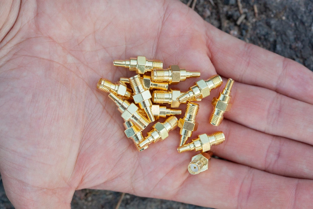
Someone drops a photo into your inbox. Zoomed-in, slightly blurry, a metal nub sitting on a green board or dangling off a coax pigtail. "What connector is this?" they ask, and now you're squinting at pixels trying to decide if that's a thread or just a shadow. We've all been there. Maybe you're ordering a replacement pigtail, maybe you're laying out a board and need to match an existing footprint, maybe you're just curious. Either way, there's a repeatable way to work through this puzzle from a single image, and we're going to walk through it. We'll also tell you honestly when a photo simply won't cut it and calipers become mandatory.
Why bother with visual ID at all
Here on Green Button we spend our days living among MMCX, MCX, U.FL, IPEX, MHF, SMA, SMB, SMP and a handful of other miniature RF interconnects that all look suspiciously alike if you're not paying attention. And that's precisely the danger. Mate the wrong pair, force a connector that was never meant to seat with another, and you risk bent pins, cracked dielectric, or a connection that "works" but leaks RF performance all over the floor. Some of these families will physically jam together and still refuse to actually mate. This piece is about training your eye to catch the tells before you reach for the soldering iron.
The visual checklist worth memorizing
Start with coupling method, because it narrows things down faster than anything else. Is there a threaded collar? Look for parallel ridges running around the outer shell, tiny and fine on SMA, coarser on some SMB variants that use screw-on options. A smooth cylindrical shell usually means snap-on or push-on, the MMCX and MCX territory. Bayonet lugs stick out like little tabs, unmistakable once you've seen one. Press-fit and surface-mount connectors sit flush against a board with no visible shell protrusion at all, just a footprint.
Scale is your next clue, and photos lie about scale constantly unless there's a reference object. A coin, a ruler, even a known-size screw in frame tells you everything. Without one, look for a coax jacket in the shot; jacket diameter is a decent proxy. U.FL sits at the ultra-tiny end of the spectrum, MMCX and MCX a notch up, and SMA, SMB, SMP considerably larger and chunkier by comparison.
Then there's the center conductor. A protruding pin means male. A recessed hole or socket means female. Note the dielectric ring around it too, its color and shape (white PTFE, beige, sometimes a molded plastic collar) can help narrow manufacturer or series once you cross-reference datasheets.
Outer shell geometry deserves its own glance: hex flats suggest a connector meant to be torqued down with a wrench, knurling suggests hand-tightening, a smooth ring with no texture often points to snap-on retention. And don't ignore the back end. Solder cup, crimp barrel, PCB through-hole pads, or a surface-mount footprint all tell you how this thing terminates, which in turn tells you what family it likely belongs to.
Lastly, hunt for markings. Tiny embossed logos, part numbers, moulding marks. These are gold. Google them directly and half your work is done.
A workflow you can actually follow
Step one, get the right angles. A single face-on shot is rarely enough. Ask for (or take) a face-on view of the center pin, a side profile showing the coupling mechanism, a rear view of cable or board, and a macro shot of any threads or locking tabs.
Step two, introduce scale. A coin next to the connector works wonders. So does a ruler laid flush against it.
Step three, classify by coupling type first, size second. This alone eliminates most wrong guesses.
Step four, compare against reference photography, ours or a manufacturer's datasheet gallery works fine.
Step five, search the part number or distinguishing feature, and if that dead-ends, post it to a forum with your photos attached.
Look-alikes that trip people up
MMCX and MCX are the classic mix-up, both push-on, both roughly cable-end connectors, differing mainly in outer shell diameter, a distinction that vanishes in a low-resolution photo. U.FL, IPEX, and MHF get confused with miniature MMCX on crowded boards, but U.FL sits ultra-low-profile with a rectangular mating footprint versus MMCX's round cable-end housing. SMB, SMP, and SMA get lumped together despite wildly different coupling styles, SMB snaps, SMA threads, SMP push-fits in tight, high-density board arrangements. And always verify if you're looking at a jack or a plug from the rear; that single detail flips your whole identification!
Watch for glare hiding thread ridges, a foreshortened angle hiding hex flats entirely, or a cropped frame cutting off the cable jacket you needed for scale.
When photos just won't do it
Sometimes you need more than pixels. Ask for the cable's outer diameter, the board's mounting hole diameter, any nearby part numbers silkscreened onto the PCB. And honestly, if precision actually matters, get calipers on the part or send it to a lab. Guessing from a photo is a starting point, not a certification.
Tools worth having
Use manufacturer datasheets, distributor filter tools from the likes of Mouser or Digi-Key, and yes, RF-focused forums where people are generally happy to help if you post clear photos with scale included. A macro lens attachment for your phone plus a cheap ruler will save you more headaches than you'd expect.
Two quick examples
A Wi-Fi card photo shows a tiny rectangular receptacle soldered flush to the board, practically invisible in profile. That's your U.FL/IPEX signature.
A round, knurled cable-end connector with an exposed male pin and a push-on retention ring, no threads anywhere? That's almost certainly MMCX rather than MCX, once you confirm the outer shell diameter against a known reference.
The cheat sheet
Coupling method first, then scale, then center conductor style, then shell geometry, then cable or board termination, then confirm against a datasheet. That order rarely fails you.
Send us your mystery connector
Got a photo of something you can't place? Send it our way, multiple angles, something for scale, and a note on the cable or board it's attached to. We're also working on a guide covering which connectors will physically mate but shouldn't, so stay tuned for that one.