MMCX vs MCX: Real-world differences beyond the datasheet
They look almost identical, both snap into place with that satisfying little click, and yet we've watched technicians grab the wrong one off a bench a dozen times over. Here's the thing nobody tells you until you've stripped a center pin right before a demo: the datasheet is a starting point, not a survival guide. This piece comes from years of us swapping these connectors on prototypes, crying at cross-mate attempts, and occasionally winning. What follows is the version we wish someone had handed us years back, before we learned it the hard way on our own bench.
TL;DR
MMCX is the smaller sibling, easier to lose, trickier to hand-mate, and a little less forgiving under repeated stress. MCX gives you more real estate to work with and tends to survive rough handling better. Both are snap-on. Neither will mate with the other despite looking like cousins. Pick based on your footprint budget and how many hands will touch that connector in its lifetime.
What the datasheet actually tells you
Both families trace back to the same design pressure: engineers needed snap-on RF connectors smaller than SMA/SMB, and needed them fast, as devices kept shrinking through the 90s and 2000s. MCX arrived first as a compact micro connector; MMCX followed as an even tinier variant for applications where every square millimeter of board space mattered.
Datasheets will quote you 50 ohm nominal impedance, frequency ratings that climb into several GHz, and mechanical descriptions that sound bulletproof. Fine. Those numbers assume a pristine connector, mated perfectly straight, tested in a lab with zero cable stress. Reality involves shaky hands, bent pins, and someone yanking a cable sideways because the enclosure didn't leave enough clearance. That gap between the spec sheet and the workbench is where this whole article lives.
What you'll actually notice in the lab
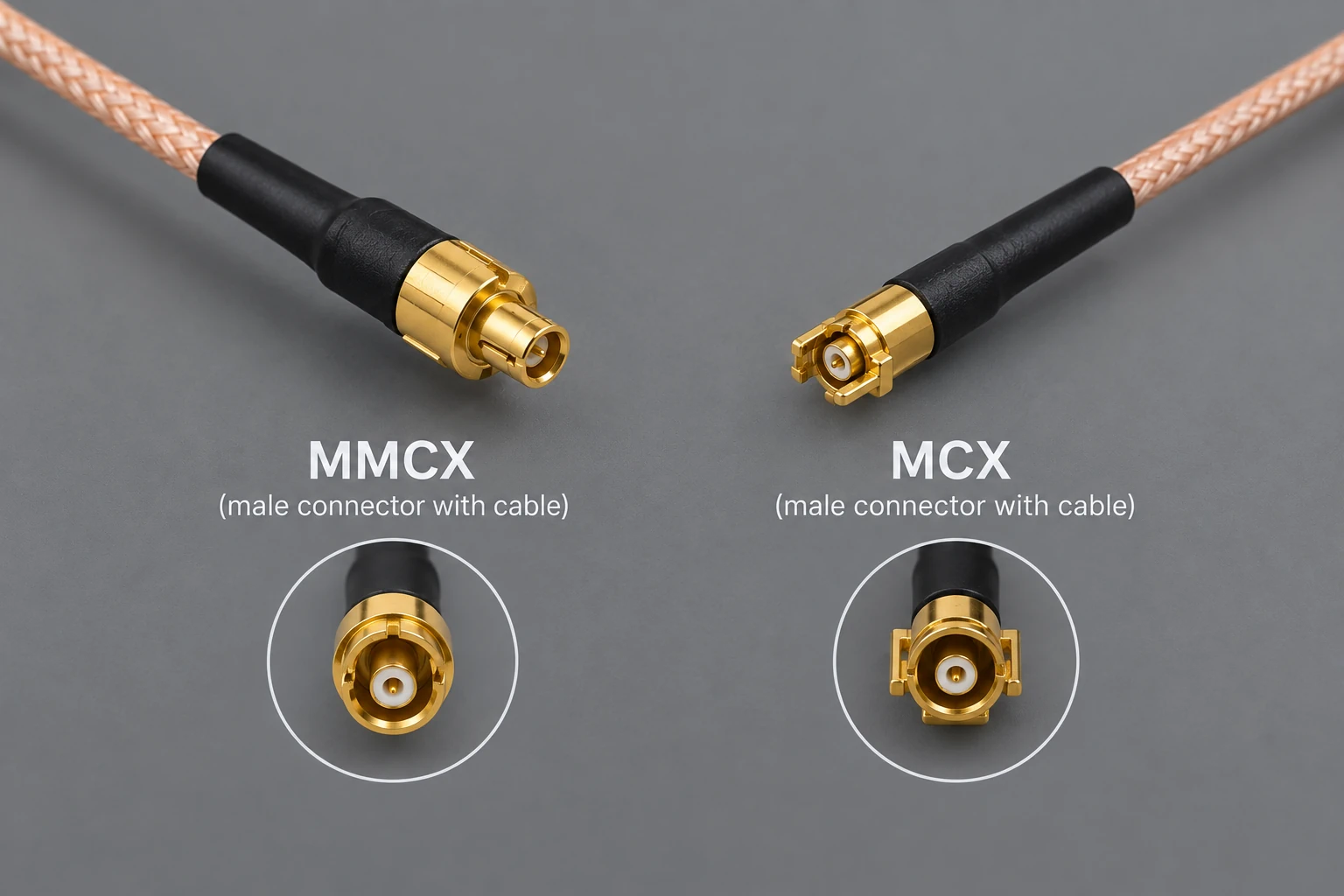
Pick up an MMCX and an MCX side by side and the size difference is obvious. MMCX measures around 2.5mm across the coupling nut area versus MCX's roughly 3.5mm. Doesn't sound dramatic until you're hand-placing a dozen of them under a microscope, or your pick-and-place machine keeps rejecting parts because the tolerance stack is unforgiving at that scale.
Both use snap-on coupling, no threading, no torque wrench required. But the retention feel differs. MCX gives a firmer, more confident click. MMCX's smaller spring contacts mean the coupling force is gentler, which is lovely for repeated mating but leaves it more susceptible to working loose under vibration if the cable isn't strain-relieved properly.
Mating cycle ratings on paper often look similar, somewhere in the 100 to 500 cycle range depending on manufacturer. In practice, we've seen MMCX center pins deform well before that number if someone mates it at even a slight angle. MCX tends to forgive a sloppier hand. The most common casualty in either family is the tiny spring finger contact losing its temper (literally, in the metallurgical sense) after enough insertions.
Electrical behavior once real cables get involved
Insertion loss numbers on the datasheet are measured under conditions you will never replicate in a finished product. Cable quality, how well the connector was terminated, if the crimp was done properly, all of that swamps the tenths-of-a-dB differences you see quoted between connector families.
Partial engagement is the silent killer here. An MMCX that looks seated but isn't fully clicked can show a return loss that's noticeably worse than spec, and it won't necessarily be obvious by eye. Side load on the cable, especially with MMCX's smaller mating interface, translates into angular misalignment at the contact point, which shows up as intermittent signal rather than a clean failure. That's the maddening kind of fault, the one that vanishes when you wiggle the cable to inspect it.
Shielding-wise, size cuts both ways. Smaller connectors have less shell surface contact area, which can mean slightly more susceptibility to leakage at higher frequencies, though in most practical builds this is a minor contributor next to poor grounding elsewhere in the assembly. Frequency ratings quoted into the several-GHz range assume the connector, not the cable transition or the solder joint feeding it. Those junctions are usually the actual bottleneck.
Compatibility traps and the "why won't this go in" moment
Straight answer: MMCX and MCX do not mate. The dimensional mismatch is significant enough that forcing them together risks damaging the female contact permanently, not just failing to connect. The center pin geometry and shell diameter are simply built to different rules.
This confusion isn't limited to these two. People try jamming U.FL into MHF footprints, or SMB against SMP, assuming "small RF connector" is basically one category. It isn't. Each has its own contact geometry, its own coupling tolerance, and forcing a mismatch usually ends with a bent pin or a cracked dielectric that you won't notice until the RF performance goes haywire.
Adapters exist for legitimate cross-family needs, and they're fine when used sparingly, but every adapter is another insertion loss contributor and another mechanical joint that can work loose. Before mating anything, a quick visual check, look for consistent contact color, no bent pins, shell alignment - saves you from a lot of grief later.
Sourcing, assembly, and the quality control gap
Not all MMCX or MCX connectors are created equal. Plating thickness, spring temper, and shell tolerances vary between suppliers more than most people expect, and cheaper batches show it in mating feel almost immediately. Crimp termination is common for cable assemblies in both families, though solder and press-fit versions show up for PCB-mount applications. Sloppy crimping is probably the single biggest quality issue we've traced RF problems back to.
On the board side, keepout zones and proper mechanical support around the connector footprint matter more than people budget for early in layout. A connector with no board-level strain relief will eventually crack its solder joints from cable movement, full stop. Add basic incoming inspection: a continuity check, a visual pass, and a quick RF sweep on a sample from each reel.
Field fixes and troubleshooting
For intermittent connections, start with the obvious: visual inspection, a gentle wiggle test while monitoring signal, then continuity. Isopropyl alcohol on a swab handles most contamination without touching the plating. Avoid abrasive tools near the center pin, it's more delicate than it looks.
Re-crimp if the termination itself is suspect; replace the whole assembly if the shell is deformed or the dielectric looks compromised. Zip-ties and tape are fine as stopgaps but they mask strain problems rather than solving them, and an adapter used as a permanent fix instead of a temporary one just adds a failure point you'll deal with later.
Quick decision guide
Need the smallest footprint possible and can guarantee careful handling? MMCX. Need something more tolerant of rough field use, frequent remating, or less delicate assembly work? MCX. Vibration-heavy environments lean MCX. Ultra-compact consumer modules lean MMCX. Cost is usually a wash between them, so let the mechanical environment decide.
Takeaways
Size drives almost every practical difference between these two, from handling to failure mode. They will not cross-mate, so don't try. And the datasheet is only the beginning of the story - the real test happens on your bench and in the field! Grab samples from a couple of vendors, run your own mating cycle test under your actual conditions, and bring connector choice into your mechanical design conversation early rather than as an afterthought.