Detecting intermittent vs permanent connector faults in wireless products
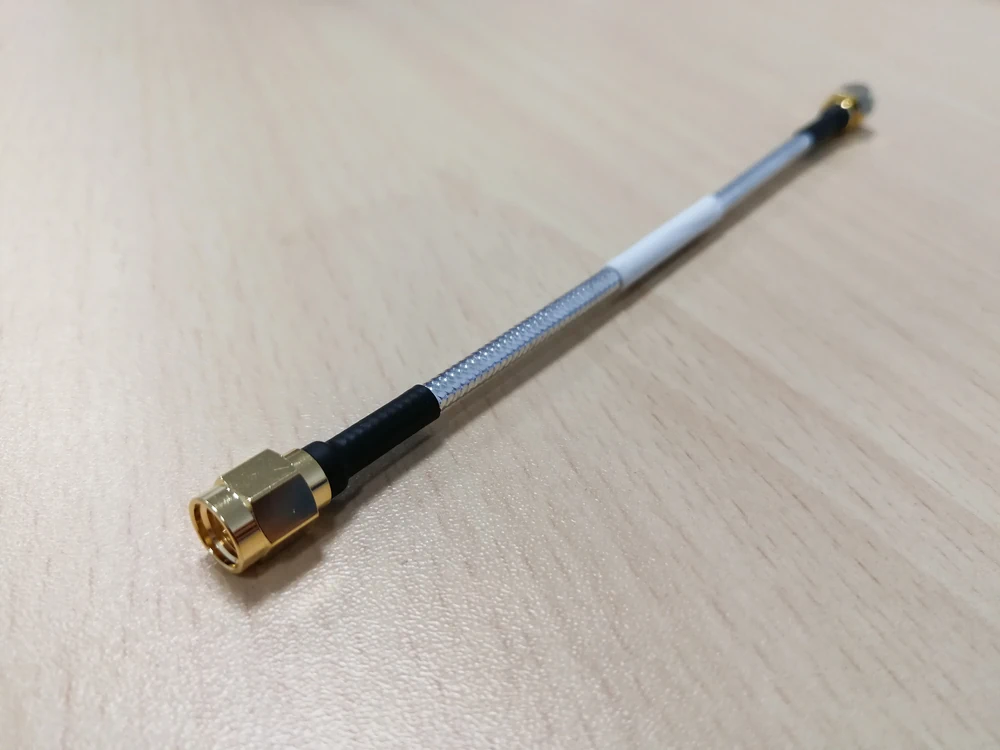
Here's the deal: a connector that fails once and stays dead is annoying but honest. A connector that fails only when someone breathes near it, walks by with a coffee, or the temperature drifts three degrees? That's the one that'll ruin your week. This piece walks through how to tell the two apart, using tools you probably already have on the bench, plus a few you should buy if you're serious about miniature RF work.
What we actually mean by "intermittent" and "permanent"
Quick definitions before we go further, because engineers argue about this more than you'd think.
An intermittent fault comes and goes. Wiggle the cable, and suddenly your signal's back. Heat the board up five degrees, and the dropout reappears. Classic culprits: a hairline crack in a center pin, a spring contact that's lost just enough tension to make contact iffy under vibration.
A permanent fault, by contrast, just sits there being broken. Snap the center conductor clean off, corrode a contact into oblivion, and you've got a fault that isn't going anywhere until somebody fixes it.
Connectors earn their own chapter in the failure-mode textbook because the tolerances involved are laughably tiny. A U.FL socket has maybe a few hundred mating cycles in it before things start going sideways. Plating wears. Springs fatigue. And all of this happens at frequencies where a fraction of a millimeter of misalignment turns into measurable return loss.
Why bother telling them apart
Because the fix is completely different, and so is the bill. Chase an intermittent fault like it's permanent, and you'll swap parts forever without solving anything. Treat a permanent fault like it might just need a wiggle and a prayer, and you'll ship product that fails audits, or worse, fails in someone's hand three months after purchase. There's also a regulatory wrinkle nobody likes talking about: a connector degrading slowly can push emissions or receiver sensitivity out of spec without tripping any alarm on the production line. That's the kind of thing that turns into a very expensive phone call.
How the trouble usually announces itself
Symptoms tell you almost everything if you know how to read them. Random dropouts that vanish and reappear point toward intermittent behavior nine times out of ten. A steady, unchanging loss of signal, gone and staying gone, smells permanent. Watch for frequency-dependent degradation too: if only your high-band performance tanks while everything else looks fine, that's often a mechanical alignment issue rather than outright breakage.
Movement is the tell-tale sign for intermittent faults. Bend the cable, apply light pressure near the connector, change the ambient temperature, and if the fault dances in and out, you're dealing with something mechanical and marginal.
Progressive degradation, on the other hand, where things get steadily worse over days or weeks of use, usually means corrosion or wear grinding toward a permanent failure.
And don't ignore the acoustic evidence either: intermittent noise, spurs that come and go, a bit error rate that spikes randomly, these all differ from a constant, boring, high insertion loss that never budges. U.FL connectors love to just pop loose under stress. MMCX connectors, after enough mate-demate cycles, develop a snap that's lost its snap.
Instruments worth having within arm's reach
You'll want a mix of mechanical and electrical gear. On the mechanical side: a torque wrench sized for your connector family, a loupe or microscope (cheap USB ones work fine for a first pass), maybe a borescope if you're chasing something buried in an assembly, and proper cleaning swabs, because contamination masquerades as failure more often than people admit.
Electrically, a VNA is non-negotiable. Return loss, insertion loss, VSWR, all of it lives there, and sweeping across your operating band beats a single-frequency spot check every time.
A spectrum analyzer paired with a modulated source lets you run BER or PRBS tests that catch things a static S-parameter sweep might miss. Time-domain reflectometry earns its keep when you need to pinpoint exactly where along the cable a discontinuity lives.
A multimeter, ideally four-wire, checks DC continuity and contact resistance, though fair warning: DC continuity can look perfectly healthy on a connector that's an absolute disaster at 2.4 GHz. So don't let a clean ohmmeter reading lull you into complacency!
An oscilloscope catches transients during a wiggle test. And if you've got access to a temperature chamber or even just a heat gun and a freeze spray can, use it.
The workflow that actually works
Start by writing everything down. Symptoms, firmware version, which cable and antenna, operating conditions, photos of the connector and its mating history. I know it sounds tedious, but saves many hours later.
Then try to reproduce the fault on the bench. Wiggle it, bend it, warm it up, cool it down. Note if the failure is reproducible on command, repeatable under specific conditions, or genuinely random. Swap in a known-good antenna lead here too, just to rule out the cable.
Next comes the quick stuff: visual inspection under magnification, checking for dirt or a bent center pin, a fast continuity check, and a single-frequency VNA reading to spot anything glaringly wrong. If nothing jumps out, escalate to a full instrumented pass. Run the complete S-parameter sweep and compare against a golden sample you trust. Use TDR to locate reflections. Run a throughput test while physically flexing the connector, and determine if packet loss lines up with the mechanical stress.
If you're still stuck, isolate methodically. Swap the suspect pigtail for a known-good assembly. Problem disappears? You've found your culprit. Problem persists? Look upstream, board-side connector, solder joint - maybe the RF front-end itself is the real offender.
Finally, stress it. Repeated mating cycles, temperature cycling, even a bit of vibration if you've got the rig for it. This is how you find out if today's intermittent issue is tomorrow's permanent failure. Keep records of every pass and fail. Future-you will thank present-you.
Connector-by-connector quirks worth knowing
U.FL, IPEX, and MHF connectors have laughably low mating durability, somewhere in the low hundreds of cycles for many parts. Intermittent behavior here is frequently just partial seating or a center contact that's taken a slight bend from an impatient hand. Use the proper insertion tool, photograph your work, and resist the urge to unplug and replug "just to check."
MMCX and MCX connectors suffer from snap fatigue over time, the retention spring simply loosening its grip after enough cycles. This tends to show up late in a product's service life rather than out of the box, so factor that into your test planning.
SMA and SMB connectors fail differently, usually more decisively. Cross-threading, shoulder damage, a cracked dielectric… these are typically permanent affairs from the start. A torque wrench and a careful visual check for dielectric cracking go a long way toward avoiding them entirely.
SMP connectors, being push-on designs, tend toward frequency-dependent return loss issues when misalignment creeps in, rather than an abrupt drop-dead failure.
And a general warning across all of them: contamination, be it from stray lubricant or early-stage corrosion, can absolutely wreck high-frequency performance while looking completely innocent on a DC test. Don't trust the ohmmeter alone. Ever.
Deciding when to repair or just bin it
Replace the connector or pigtail outright if you see visible damage, abnormal contact resistance, or a VNA trace that shifts significantly and then corrects itself once you swap the part. Repair, meaning clean, re-seat, or re-terminate, when the issue is contamination, a loose mate, or shoddy strain relief rather than actual physical damage.
As a rough guide: an insertion loss increase beyond half a decibel to a full decibel in your operating band, or an S11 shift of several decibels against your golden sample, is worth acting on. A VSWR creeping past 2:1 in-band, especially one that jumps around during a flex test, points toward a mechanical fault worth chasing down. Contact resistance north of 100 milliohms, measured with a proper four-wire setup and compared against baseline, usually means the contact itself has given up. These numbers shift depending on frequency and how much margin your system has to spare, so always benchmark against something known-good, rather than trusting a number in isolation.
Building it right the first time
Pick the connector family that actually suits your expected mate cycle count, torque to spec every single time, and don't skimp on strain relief or PCB anchoring. Gold plating and corrosion-resistant alloys cost a little more upfront, but save you a great deal of grief down the line. And if your product ships with any kind of telemetry, log RSSI and BER in the field. Catching an intermittent fault trend before it becomes a warranty flood is worth more than almost any other design decision you'll make this year.
When to hand it off and the short version
Escalate to a vendor or dedicated lab when the fault survives a full harness swap, when you suspect the defect lives inside the RF module itself, or when field returns start showing a pattern rather than isolated incidents. The whole process, boiled down: reproduce it, isolate it, instrument it, replace what needs replacing, stress test what's left, and write it all down as you go.
Start with a reliable reference cable and a genuine attempt to reproduce the fault before you touch anything else. A wiggle test paired with a VNA sweep tells you more in ten minutes than an afternoon of guessing. And when in doubt about a miniature connector that's being flaky, just replace it. Chasing ghosts in a part that costs less than your coffee rarely pays off.