Cable assemblies for MMCX and U.FL: choosing the right coax for the job
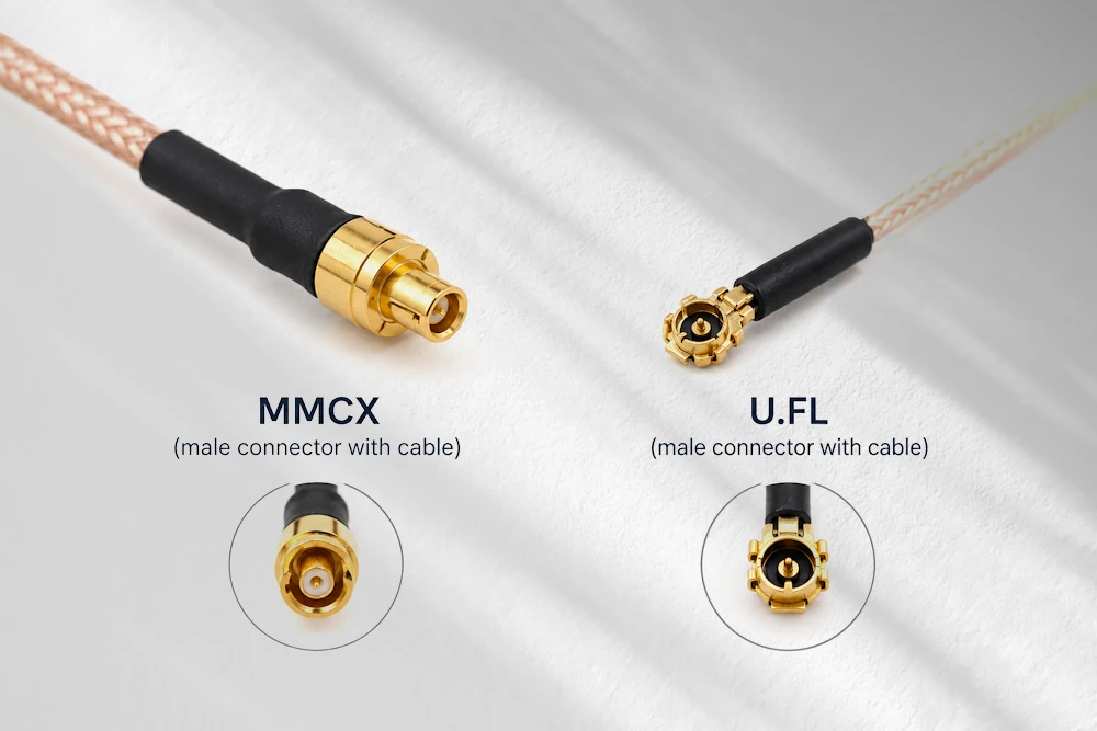
Picking a connector is the easy part. The coax dangling behind it is where most RF headaches actually live, and if you've ever chased a mysterious 3 dB loss through a board revision, you already know this. Here's a working guide to matching cables for MMCX and U.FL builds, without the guesswork.
Why this keeps tripping people up
Walk into any module design review and you'll hear plenty of chatter about connector footprints, keep-out zones, mating orientation. Almost nobody talks about the cable itself until something fails a range test. MMCX and U.FL have become the default miniature interconnects for Wi-Fi modules, GNSS pucks, IoT gateways, test fixtures, basically anywhere board space is scarce and an external antenna is unavoidable. But the connector is only half the circuit. Choose the wrong coax and you can build a technically correct assembly that still performs like garbage in the field. What follows is a compact framework: how to think about frequency, flex life, routing constraints, and where these two connector families tend to land in real products.
MMCX and U.FL, side by side
Quick refresher, because the two get lumped together constantly despite being fairly different animals.
MMCX sits around 9mm across at the mating interface and uses a snap-on bayonet-style coupling, rated for roughly 100 to 500 mating cycles depending on manufacturer.
U.FL (and its cousins like MHF and IPEX) is smaller still, a friction-fit micro-connector rated for maybe 30 cycles before you start risking damage to the board-mount receptacle. That number alone should tell you something about intended use.
U.FL lives inside enclosures: module-to-antenna jumpers, laptop Wi-Fi cards, small drones, places where a cable gets mated once at the factory and never touched again. MMCX shows up more on pigtails meant to be handled, on test benches, in RF switch matrices, anywhere a human is expected to plug and unplug things with some regularity. Neither wants to be treated like an SMA connector, so if your assembly process involves someone yanking on the cable to disconnect it, you've already made the wrong call somewhere upstream.
The parameters that actually decide the outcome
Before touching a coax datasheet, get clear on what you're optimizing for.
Electrically, you care about characteristic impedance (virtually always 50 ohms in this space), attenuation across your frequency band, return loss, shielding effectiveness, and the dielectric's velocity factor - if phase matching matters to you.
Mechanically, it's bend radius, flexibility, how much crush resistance you need, operating temperature range, and whether the assembly will see vibration in the field.
Then there's the part everyone forgets until the pilot run: can this cable actually be terminated consistently? A gorgeous low-loss cable that nobody on the line can solder without voiding the shield integrity is worse than a mediocre cable terminated well. Impedance discontinuities love to hide exactly at the cable-to-connector transition, and that's usually where a sloppy stripping job or an oversized ferrule quietly wrecks your VSWR.
The usual suspects: coax families you'll actually encounter
Standard small coax, the RG174/RG316 family, is the workhorse for MMCX pigtails and external antenna leads. It's thicker than the micro-coax options, genuinely easy to terminate, and forgiving of rough handling. The tradeoff is a larger minimum bend radius and higher loss per foot, so it's not your friend on long runs at higher frequencies.
Micro-coax in the 1.13mm OD range is the natural partner for U.FL. It threads through tight internal routing, tolerates the kind of folding and squeezing that happens inside a plastic enclosure, and gives you a reasonable loss-to-flexibility tradeoff for short jumpers. Crimp or solder-crimp termination is standard here, but ferrule sizing matters more than you'd think. Get it slightly wrong and you'll either crush the dielectric or leave a gap that becomes an impedance bump.
Ultra-thin micro-coax, around 0.81mm OD, exists for the genuinely cramped jobs: wearables, tiny modules, anywhere routing space is measured in millimeters. It's fragile, attenuation climbs noticeably, and strain relief becomes non-negotiable rather than a nice-to-have.
Semi-rigid and semi-flexible coax belongs on the test bench, not inside a product. When you need rock-solid, repeatable impedance for lab work or precision RF test leads, semi-rigid earns its bulk and stiffness. It's not something you'd route through a phone chassis, but for calibration cables and fixture interconnects it's often the correct answer.
As a rough map: U.FL pairs naturally with 1.13mm or thinner micro-coax; MMCX pairs comfortably with RG174/RG316 or occasionally semi-rigid for lab adapters.
Mechanical realities and how they bite you later
Mating cycles matter more than most BOMs acknowledge. U.FL receptacles are not built for repeated disconnection, full stop. Treat them that way in test fixtures and you'll eventually crack solder joints or shear the shell off the board pad. MMCX gives you more headroom, but "more" isn't "unlimited."
Bend radius deserves a rule of thumb: for micro-coax, keep your minimum bend radius at roughly ten times the cable OD, not the three-to-five times ratio you might assume from thicker cable. It looks flexible right up until the copper braid work-hardens and the shield starts cracking internally, invisible until your loss numbers drift. For anything exposed to vibration, don't rely on the connector's friction fit alone; add adhesive dots or a proper strain relief boot.
Making sure the pieces actually fit together
Before signing off on any assembly, run through physical fit: cable OD against the connector's crimp ferrule or boot, center conductor diameter, correct dielectric strip length. Then verify electrical continuity end to end, confirming that 50 ohms holds through the crimp or solder transition, not just on paper. Document the exact assembly method, crimp tool and die, or specific soldering technique, since inconsistent termination is the number one reason two "identical" pigtails from different vendors behave differently on a network analyzer. This is also why swapping in a cheaper MMCX or U.FL pigtail from an unfamiliar supplier can quietly wreck a design that worked fine with the original part.
Recommended pairings that just work
For a short internal jumper on a Wi-Fi or BLE module, U.FL with 1.13mm micro-coax gets you compact routing without excessive loss.
For an external pigtail feeding an outdoor antenna, MMCX with RG174 or RG316 gives you something rugged enough to survive field handling and easy enough to weatherize with heat shrink or potting.
For test leads or anything demanding tight, repeatable performance at higher frequencies, semi-rigid cable terminated to MMCX adapters is the sensible choice.
When prototyping, buy pre-made pigtails from a supplier you trust rather than rolling your own, but the moment you move to production, lock down the exact part number. "Similar cable, different day" is how field returns happen.
Testing before you trust it
At minimum, sweep insertion loss and return loss across your actual operating band, don't assume the datasheet numbers survived your termination process. Check continuity and look for shorts. Visually inspect ferrule seating, solder fillets or crimp compression, and confirm the outer insulation hasn't been nicked during stripping. For production runs, pull samples across the batch and measure variation rather than trusting the first article alone; a time-domain reflectometer earns its keep on any run where impedance consistency is genuinely under question.
Specifying it so nobody guesses
Your BOM or datasheet request should spell out cable family and OD, dielectric material, attenuation at your key frequencies, rated mating cycles, and the recommended crimp tooling with a real manufacturer part number attached.
Watch out for suspiciously cheap pigtails, particularly U.FL ones, that mate poorly or show erratic impedance under load. Ask any new supplier for mating compatibility data and physical samples before committing to a production quantity.
Wrapping it up
Choosing coax for MMCX or U.FL assemblies comes down to balancing RF performance against mechanical demands against what your assembly line can actually terminate reliably. Run through this before finalizing: frequency range and loss budget, minimum bend radius for your routing, expected mating cycles, termination method, and if your supplier can actually prove the part performs the way the datasheet claims.
Cheat sheet: when to pick what
- U.FL + 1.13mm micro-coax: internal modules, short runs, factory-terminated once and left alone.
- MMCX + RG174/RG316: external pigtails, outdoor antennas, anything a technician might handle.
- Semi-rigid: lab and test environments where impedance stability outranks flexibility.